Project Description
– Type: LP – 9000 1600 X 4000 Fe 0,5 / 110
– Volume of the vessel: 8860 lit … total / 6645 lit … useful
– Operating parameters: 0,1 bara … 45 oC … 16,16 à 20,20 m3/h
– Design parameters: 0,5 barg … 110 oC
– Minimum condition: 0,05 bara … 32,9 oC
– Vacuum Air Condenser type: ACVC Pr 50/80 12-3x27x9500 Fe/Al 0,5/200
o Nominal capacity: 0,1 bara … 45 oC … 16 t/h … 10654 kW / Air 27 oC
o Maximum capacity: 0,1 bara … 45 oC … 20 t/h … 13318 kW / Air 27 oC
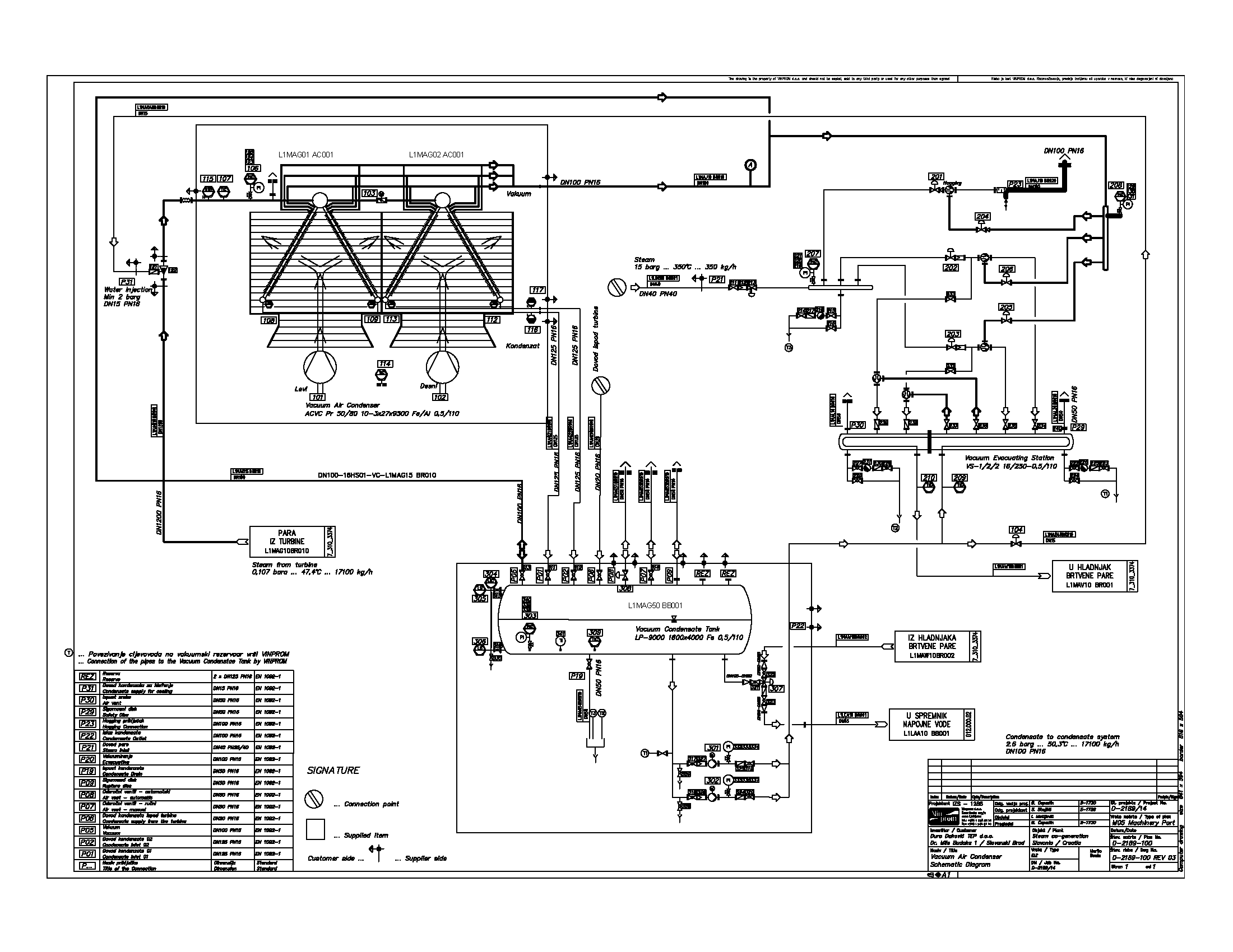
Opis sistema
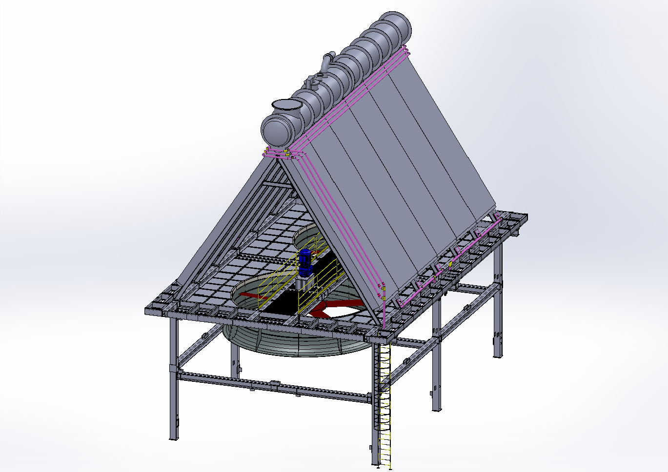
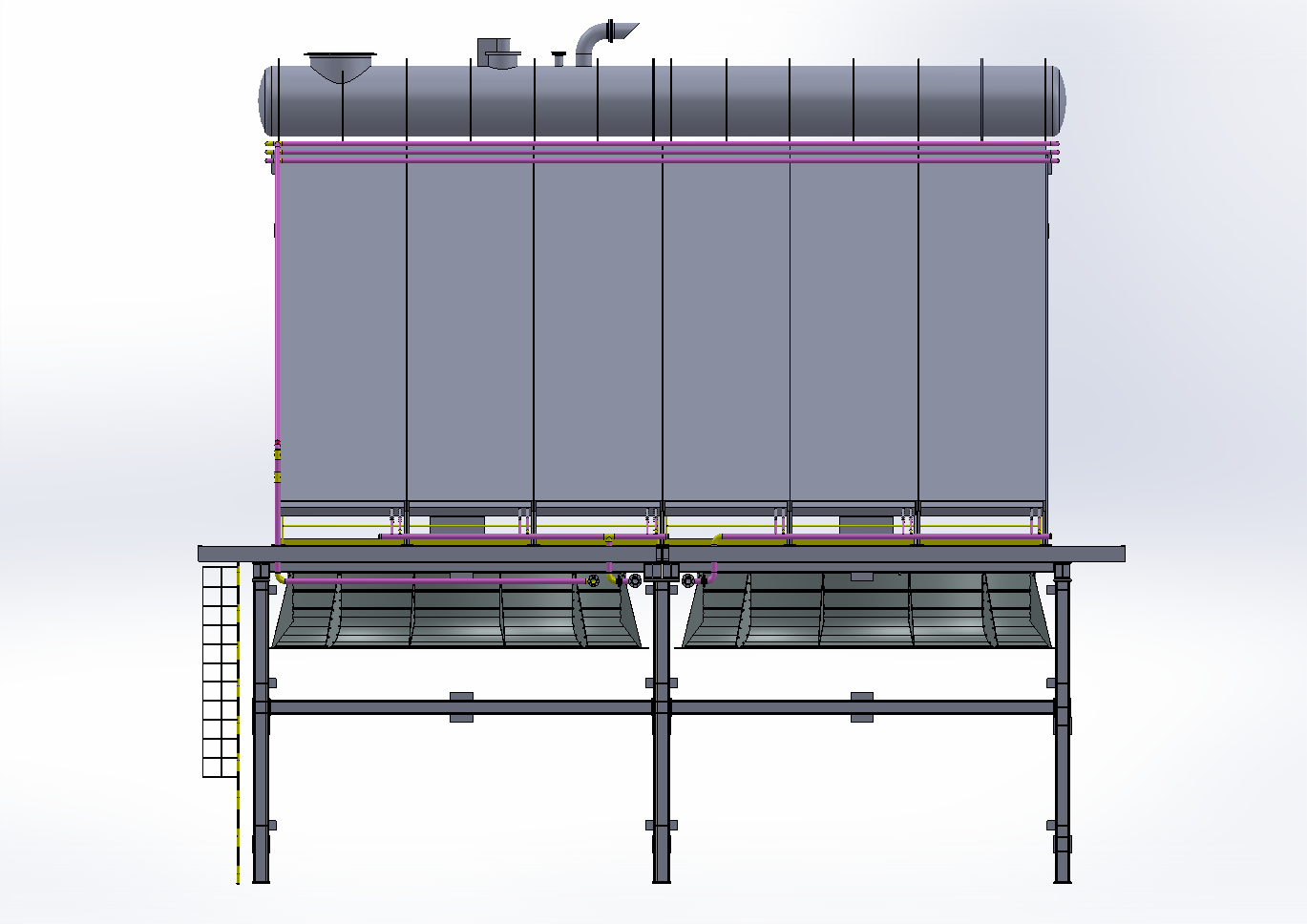
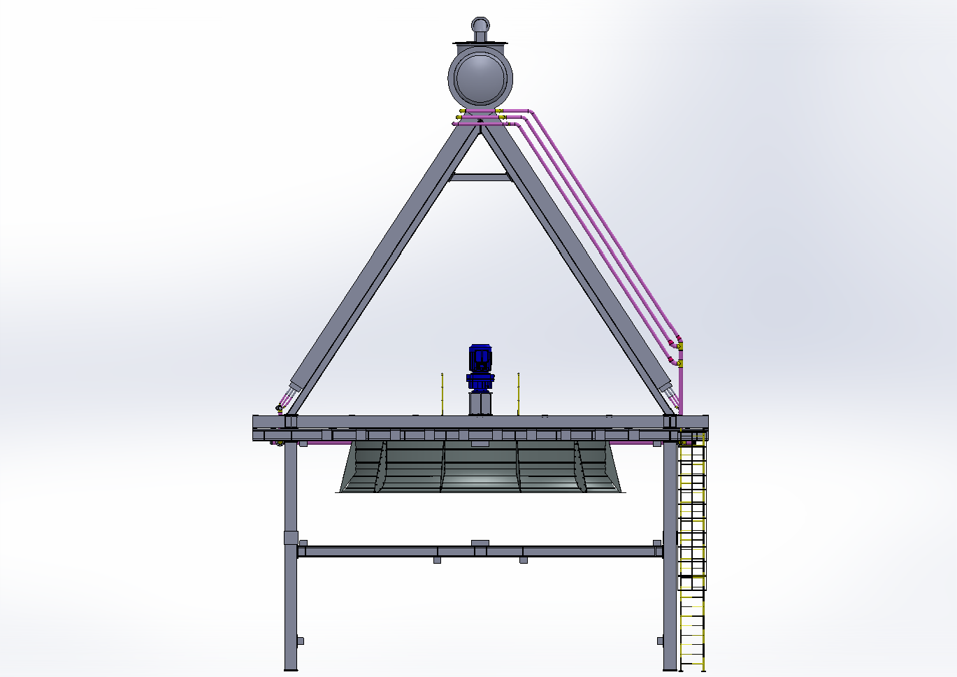
The superheated steam under the low pressure above 0, bara is flowing to the vacuum air condenser. The steam has to be cooled down close to saturation temperature by water injection unit supplied as a loose part and installed by the installer to the steam pipe. The low pressure steam is coming to the main distribution tube diameter of Ø1400 mm. The condenser units are split to the left and right side under the angle and fix welded to the distribution pipe. In addition the distribution pipe is separated to the two sections by motorized closing flap in order to provide better operation in winter time. Condenser units are manufactured as a finned pipe heat exchanger with high quality steam pipes and aluminium fins. The steam – condensate is flowing thru the pipes and air is circulating around the pipe. Special air purge system supports evacuating non-condensable gases from the system. Special draining system provides also freeze protection in winter time.
Vakuumska postaja opis
The vacuum Evacuating Station provides evacuating non-condensable gases from the system. The station consists of hogging steam ejector for fast start – up and two (2) parallel two stage vacuum ejectors.
The vacuum evacuating station is providing the system start – up within 15 … 25 minutes, and continuous smooth removal of non-condensable. The unit is operating fully automatic without any human intervention. The unit is delivered as finished assembly already painted but without insulation. All connections are finished with counter flanges PN16 according the standard EN 1092-1 (11
Toplotna postaja parametri:
– Heating capacity: 2 x 4000 kW
– Hot water inlet: 160 oC
– Hot water outlet: 180 oC
– Hot water pressure: 15 barg
Opis
The heating station is presented on the schematic diagram D-2211-000. The steam is entering via steam distributor to the pneumatic driven steam regulating valve. Steady control electro pneumatic positioning unit is regulating the steam flow to the heat exchanger according the outlet hot water temperature (set point temperature for example adjusted to 180 oC). Steam is condensing around the tubes in the condenser shell. The condensate is falling down to the bottom of the condenser and to the entrance of the cooler. The condensate regulating valve which is also pneumatic driven with electro pneumatic positioning unit is keeping the constant level of the condensate. Hot condensate is flowing across the tubes of the cooler, when the hot water is circulating around the tubes of the cooler.
Project Details
- Client Đuro Đaković d.o.o. / Slavonija DI
- Date April 13, 2015
- Tags Projektiranje
Comments are closed.